Model Rules
After capturing the models that you want to drive, you can use the rules screen to add one or more instances of those models to your project and setup rules for them.
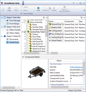
The model rules screen is divided into two areas:
- The component tree
- The rule list

To learn how to capture a model please see Captured Models
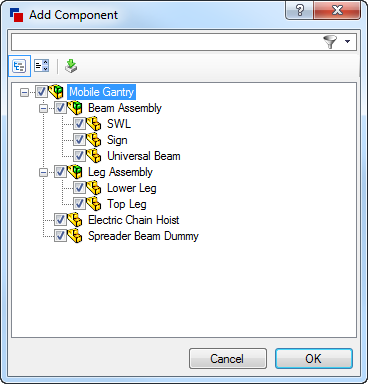
When the Model Rules task is selected, the Add Component window will automatically activate.
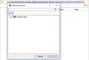
Select the component set to add to the project and click OK.
To learn how to add further models to the project please see To Add a Model to Drive below.
Each top level model should be added to the component tree first.
See To Add a Model to Drive below.
The reason for this will become clear if you start using driven replacement models to give you complete control over an assembly structure.
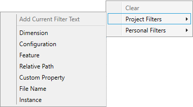
Filtering
The Component Tree and Rule List can be filtered by using the filter bar at the top of each list.

The Filter Bar above the Rule List contains presets that will enable quick filtering of common terms.
These include:
- Dimension - will display all captured dimensions for the selected components
- Configuration - will display all configurations for the selected components
- Feature - will display all captured features for the selected components
- Relative Path - will display all relative paths for the selected components
- Custom Property - will display all captured custom properties for the selected components
- File Name - will display all file names for the selected components
- Instance - will display all captured instances for the selected components
To use a preset filter term:
- From the Model Rules task, select the components to display the captured parameters for.
- From the Filter Bar immediately above the Rule List, select the filter drop down.
- Select Project Filers.
- Select the required term from the list.
Please see the topic How To Use Filters for more filtering information.
Component Preview
Model Rules will display a preview of anything highlighted in the Component Tree.
Once a component is highlighted the preview, along with additional information, is displayed in the section Component Details, directly under the component tree and rule list.
| Component Type | Additional Information | Preview |
|---|---|---|
| Assembly |
| 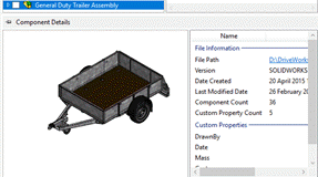 |
| Part |
| 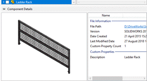 |
| Drawing |
|  |
To Add a SOLIDWORKS Assembly as a Component Set.
Checking an assembly in the Add Component dialog will check all sub-assemblies and parts automatically.
The assembly will be added to the Model List as a Component Set.
Checking sub-assemblies or parts (without checking a higher level assembly) will add those items as separate component sets.
- When checking an assembly to add, any sub-assemblies or parts were not automatically checked.
- Checking an assembly and its sub-assemblies or parts added these as separate component sets in the Model List.
This will prevent the unintentional adding of sub assemblies and parts to the captured components tree.
To Remove a Top Level Model and its Children (Component Set)
- Select the Component Set in the component tree by clicking on it.
- Click the "Delete" button on the command bar.
The model and all of its children will be removed.
To Rename a Top Level Model and its Children (Component Set)
- Select the Component Set in the component tree by clicking on it.
- Click the "Renaming" button on the command bar to start editing the Component Set name.
- Type a new name, and press Return when you are done.
To Reorder Top Level Models (Component Sets)
Component sets can be reordered to make sure that one gets calculated before another. This is useful when working with driven replacement models.
- Select the Component Set to move in the component tree by clicking on it.
- Use the Move Up/Move Down buttons on the command bar to move it up or down.
- Alternatively use the Move To Top/Move To Bottom buttons on the command bar to move the component set directly to the top or bottom.
To Select Models to Edit
To display the rules for a model in the rules list, check the box next to it on the left hand side.
To Select Rules to Build
You can select an individual rule in the list and build it by clicking on the "Build" button on the command bar.
To Recalculate Rules
The values shown in the rule list can become out-of-date if changes are made in other tasks in the task explorer. To refresh them all, click the "Calculate" button.
To Refresh Captured Information
If you start working in the model rules screen, and then capture some more models, features, dimensions, and so on, you may need to click the "Refresh" button for them to be shown in the model rules screen.
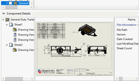
Drawing Rules
Drawing rules are built in the model rules screen which shows detailed information about the drawing, sheet, views, and so on that were captured.

The rules screen is divided into five areas, the two top sections which are used to build rules are:
- The drawing tree - this shows the drawings that are captured and what models they belong to.
- The rules list.
The three bottom areas show various information about the captured drawing such as the views that were captured, their sizes and scales and more:
- The sheets and views tree which shows will sheets, views, and view breaklines were captured. Sheets which aren't captured but are shown becomes views on them are, are shown in a dark gray color.
- The captured drawing preview which graphically shows the currently selected sheet and its views.
- The sheet/view information list which shows information that was captured about the currently selected sheet or view.
To Add a Drawing
Drawings are automatically added to the drawing rules screen when their parent models are added to the model rules screen. You may need to click the "Refresh" button for them to become visible.
To Remove a Drawing
Drawings are automatically removed from the drawing rules screen when their parent models are removed from the model rules screen.
To Select a Drawing to Edit
Click on a drawing in the drawing tree to show its rules and captured information.
To Select Rules to Build
You can select an individual rule in the list and build it by clicking on the "Build" button on the command bar.
To Recalculate Rules
The values shown in the rule list can become out-of-date if changes are made in other tasks in the task explorer. To refresh them all, click the "Calculate" button.
To Refresh Captured Information
If you start working in the drawing rules screen, and then capture some more drawings, sheets, views, and so on, you may need to click the "Refresh" button for them to be shown in the drawing rules screen.
- Welcome
- What's New
- DriveWorks 22
- Older Versions
- DriveWorks 21
- DriveWorks 20
- DriveWorks 19
- DriveWorks 18
- DriveWorks 17
- DriveWorks 16
- DriveWorks 15
- DriveWorks 14
- DriveWorks 12
- What's New DriveWorks 12
- Form Design
- Rule Builder
- Model Rules
- DriveWorks Add-in for SOLIDWORKS
- SP1
- SP2
- DriveWorks 11
- Welcome to DriveWorks Solo 11 What's New
- Capturing
- Project Designer
- Installation
- Licensing
- SP1
- SP1.1
- SP2
- SP3
- V10
- V9
- V8
- SP0
- SP1
- SP2
- SP3
- V7
- Before You Begin
- Using DriveWorks Solo
- DriveWorks Solo Inside SOLIDWORKS
- Enabling the DriveWorks Solo Add-ins in SOLIDWORKS
- Project Wizard
- Capturing Models
- Captured Models
- Part Mode
- Assembly Mode
- Drawing Mode
- Run
- Run (Layout Mode)
- Project Designer
- Project Designer
- Stage 1: User Interface
- Stage 2: Data and Rules
- Stage 3: Output Rules
- Writing Rules
- Writing Rules
- Rules Builder
- Extract Variable
- Edit Variable
- Rule Builder Settings
- Document Rules
- Model Rules
- Model Rules Overview
- Parts and Assemblies
- File Name
- Relative Path
- Configuration
- Feature
- Dimension
- Tolerances
- Custom Property
- Instance
- File Formats
- Advanced Feature Parameter Rules
- Model Rules Advanced Feature Parameter Rules - Overview
- Boss/Base Features
- Boss/Base Thin
- Break Corner
- Chamfer
- Circular Pattern
- Coordinate System
- Cosmetic Thread Features
- Curve
- Curve Driven Pattern
- Curve Through XYZ Points
- Cut Features
- Derived Pattern
- Distance Mate Features
- Draft
- Edge Flange
- Features
- Fillet
- Hole Wizard Features
- Linear Pattern
- Local Circular Pattern
- Local Linear Pattern
- Lofted Bend
- Mates
- Mold Features
- Offset Surface
- Pattern Features
- Revolved Boss/Base
- Revolved Boss/Base Thin
- Rib
- Ruled Surface
- Sheet Metal Features
- Simple Hole
- Sketch Pattern
- Slot Mate
- Surface Features
- Sweep Thread
- Table Driven Pattern
- Var Fillet
- Weldment Features
- Wrap
- Drawings
- Functions
- Functions
- Conversion
- Cryptography
- Date and Time
- File System
- Helper
- Lambda
- List
- Logical
- Math
- Specification
- Table
- CountIF
- CSVFromTable
- Dcount
- DMax
- DMin
- DWHLookup
- DWVLookup
- GetTableValue
- HLookup
- ListAll
- ListAllConditional
- ListAllConditionalDistinct
- ListAllDistinct
- SumTableColumn
- TableAppendColumns
- TableAppendRow
- TableAppendRows
- TableAverage
- TableBreak
- TableColumn
- TableColumnLookup
- TableCombine
- TableDistinct
- TableDistinctSum
- TableFilter
- TableFilterAll
- TableFilterByList
- TableFormat
- TableFromCsv
- TableGetColumnCount
- TableGetColumnIndexByName
- TableGetDataRows
- TableGetHeaderRow
- TableGetRowCount
- TableGetRows
- TableGetValue
- TableJoin
- TableMax
- TableMaxValue
- TableMin
- TableMinValue
- TableRemoveBlankColumns
- TableRemoveBlankRows
- TableRemoveRow
- TableReplaceHeaderRow
- TableReplaceHeaders
- TableReplaceRow
- TableReverse
- TableRow
- TableSelectColumns
- TableSequence
- TableSkipRows
- TableSort
- TableSortByDate
- TableSortByList
- TableSubstitute
- TableSum
- TableTakeRows
- TableTranspose
- TableWithSequence
- VLookup
- General
- Text
- Validation
- Variables
- Knowledge Base
- Concept
- How To
- How To: SolidWorks Best Practices
- SOLIDWORKS Best Practices (KB13103019)
- SOLIDWORKS Features
- How To: Correctly Format Text
- How To: Backup a Project (KB13022601)
- How To: Change A Static Property To A Dynamic Property (KB13111201)
- How To: Create A Cut Down Project (KB17092602)
- How to: Create and Install Project Templates
- How To: Determine the Version of DriveWorks Solo
- How To: Diagnose Project Issues
- How To: Diagnose Project Issues Using On Demand Generation Report
- How To: Diagnose Project Issues Using The Form Designer
- How To: Diagnose Project Issues Using The Rules Builder
- How To: Diagnose Project Issues Using SOLIDWORKS
- How To: Drive the Color of a Part
- How To: Drive the Material of a Part
- How To: Drive the Texture of a Part
- How To: Find DriveWorks Solo License Keys
- How To: Implementation Guide
- How To: Reference Control Properties (KB16010601)
- How To: Rename a Project
- How To: Replace a Component With a Static or Driven Replacement Model
- How To: Replace An Instance With A Driven Replacement Model
- How To: Maintain Rules For An Existing Model When It Becomes A Child Of A Parent Assembly
- SOLIDWORKS Best Practices (KB13103019)
- How To: Troubleshoot Licensing
- How To: Work With Arrays
- How To: Use Filters (KB15111101)
- Info
- Form Control Properties
- Color
- Border Style
- Border Width
- Button Layout
- Caption, Text (Appearance Property)
- Caption Horizontal Alignment
- Button and Caption Width
- Character Limit
- Check Alignment, Option Alignment
- Checked
- Check Size, Radio Size, Button Icon Size, Toggle Size
- Clear Selection Allowed
- Decimal Places
- Default Value
- Display Value
- Enabled
- Error result
- File Name
- Font
- Height
- Hide Characters
- Hover, Text Underline
- Hyperlink
- Button Icon Style
- Increment
- Input Spacing
- Items
- Left
- Link Behavior
- Maximum
- (Metadata)
- Minimum
- Multiline
- Name
- Number Of Rows
- Opacity (Disabled)
- Orientation
- Override Rule
- Padding, Input Padding, Unit Padding
- Picture
- Picture (Checked), (Hover), (Selected), (Pressed)
- Picture Size Mode
- Picture Style
- Placeholder Text
- Border Radius
- Read Only
- Reverse Direction
- Selected Item
- Selected Item Removed Behavior
- Show Border
- Show Check, Show Option
- Show Limits
- Show Toggle Indicators
- Size Mode
- Tab Index
- Tag
- Text Horizontal Alignment, Toggle Alignment
- Text (Label Control)
- Text, Value (Behavior Property)
- Text, Vertical Alignment
- Thumb Image
- Tooltip Duration
- Tooltip Text
- Top
- Track Color
- Visible
- Width
- Word Wrap
- File and Template Locations
- Info: DriveWorks File Extensions (KB13022602)
- Info: File and Template Locations (KB13103001)
- Template Files
- Lists and Preferences
- Reporting
- Help File
- General Information
- Info: Dangling Dimensions
- Info: Distributing A Solo Project
- Info: DriveWorks Solo Limits
- Info: Instant3D
- Info: Keyboard Shortcuts (KB13103004)
- Info: Known Issues (KB13103005)
- Info: Legal Notices
- Info: Microsoft .NET September 2022 Update Crash (KB22101401)
- Info: Mirrored Components
- Info: SOLIDWORKS System Options (KB12121012)
- Info: Special Variables
- Info: Supported DriveWorks Versions (KB13103006)
- Info: Third Party Information And Downloads
- Info: Microsoft Windows Support
- Info: Working With SOLIDWORKS Enterprise PDM
- Glossary